


A Zero Current Switch for Inductive Loads
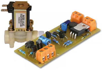
Materials
Gerber file
CAM/CAD data for the PCB referred to in this article is available as a Gerber file. Elektor Green and Gold members can exclusively download these files for free as part of their membership. Gerber files allow a PCB to be produced on an appropriate device available locally, or through an online PCB manufacturing service.
The use of our Gerber files is provided under a modified Creative Commons license. Creative Commons offers authors, scientists, educators and other creatives the freedom to handle their copyright in a more free way without losing their ownership.
Want to build a project?
Bring your design to life with the Elektor PCB Service, powered by Eurocircuits. Upload the project files and order professionally manufactured PCBs or assembled boards through a proven European production platform.
Supporting KiCad, Eagle, Gerber, and ODB++ formats, the service is suitable for everything from prototypes and validation builds to series production and volume manufacturing.
Made in Europe. Fast. Reliable. Professional.
Bill of Materials
R1 = 100 Ohm
R2 = 2.2kOhm
R3,R4 = 47kOhm
R5 = 82kOhm 1%, 0.6W 350V (Vishay MRS25000C8202FCTOO)
R6 = 220Ohm
R7 = 180Ohm
R8 = 68Ohm
R9 = 22kOhm
Capacitors
C1,C3 = 10µF 100V 20%, pitch 2.5mm, diam. 6.3mm
C2 = 10µF 63V, axial, 10 x 4.5mm
Semiconductors
D1,D2 = 1N4004
D3 = 1N4007
D4 = BZX79-C13 (13V 05W)
B1 = WO6M, 600V 1.5A
T1 = IRG4BC3OKDPbF
T2..T5 = BC546A
IC1 = PC817 (see text)
Miscellaneous
PCB # 100270
Discussion (5 comments)